
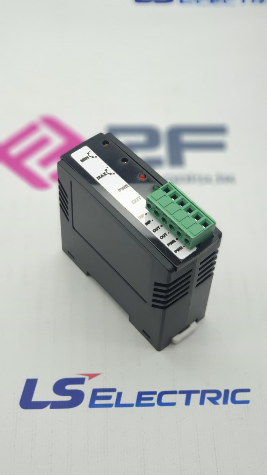


24DC-DRV technical specifications
Model-specific specifications
These values belong to the selected model record.
Operating Principle
- Operating Flow
- PLC 0-10 V analog output -> 24DC-DRV -> 24 V PWM output -> proportional load
- Operating Principle
- The PWM control ratio changes as the analog signal level rises. MIN and MAX trimmers set the operating range; the start and stop ramps control load engagement and stopping.
Electrical
- Supply
- 24 V DC
Output
- Output
- 24 V DC PWM
Control
- Control Input
- 0-10 V analog
- Control Method
- Proportional PWM based on the analog input
- MIN / MAX Adjustment
- Adjustable by trimmer
- Start Ramp
- Adjustable by trimmer
- Stop Ramp
- Adjustable by trimmer
Applications
- Proportional hydraulic valve control
- 24 V DC motor and actuator control
- Fan and pump applications
- Machine automation
- PLC-controlled variable-speed / proportional 24 V DC loads
Technical Notes and Cautions
- Technical Note
- Values such as output current and PWM frequency must be verified for the load and application. The product must be used within the current capacity required by the load.